Thursday, November 29, 2012

Reflection 7

Visit To Canon Opto Malaysia  :)


Tadaima :) Really tired for this week. Since we have wonderful trip, I feel it's worth for being tired. The journey also makes me feel impatient..it's a long journey, but quite valuable.


OK. Back to the story. Last Tuesday, on 27th November, we have a trip to Canon Opto Malaysia, also known as COM, situated at Shah Alam, Selangor Darul Ehsan. We went there by 2 buses, since almost 60 students are involved. At that time, I feel really excited because we are going to visit its factory. It means, I can see many workers and also equipments involved in order to produce a good camera.


After we reached there, there are many staff that greet us with a warm smile. We also invited to take a picture together. There are many of them bring along together their camera to take the picture of buildings and also the factory. After taking picture session was over, we were invited to main hall. At there, we were given some explanation, rules and regulations that we must obey.First of all, we are given a speech by the representative of Canon Opto Malaysia, Puan Zarina. After that, she invite the one of an engineer there to give us some explanation about rules and regulations that we must obey to avoid any accidents happen.  Since there are many place involved in the factory, we are having two session in order to visit almost all the place. Some of the place is very unique, such as Water Treatment Plant that divided two 4 phases in order to make it functions well. Besides, for second session, we visit the factory that produce camera. This factory also divided into sub-phases, such as making lens, making body of camera and also alignment for sharp image. We also are given a chance to see the region where they do the alignment for the image formed.
Also, we are having a great time when we are introduced to some code for latest camera like ec355 and ec319. Both of theses code are for digital camera, not the DSLR one.


Digital camera

DSLR camera


After we were having fun with our visit, we were back to main hall. There are all the staffs and engineers, waiting for us to briefing what we have visit before. Puan Zarina also had delivered souveniers to all of the students involved. We were also very happy because all of the students and staffs show their commitment along the process while being there.

"The happiest of people don't necessarily have the best of everything; they just make the most of everything that comes along their way." - Karen S. Magee


- Thanks a lot to Dr. Kamal and En. Redzuan =) -


Thursday, November 22, 2012

Reflection 6


 ELECTRONICS SYSTEM IN INDUSTRY


I love this week :)  Why ? Because we have another invited speaker came and delivered awesome speech to all of us. Topic for this week really inspired me to know electronics more deeply. 

Ok, let’s move to my story  ^_^.


Our speaker this week is Mr. Vivek Panicker, an Executive Director from Titan Thermal Solutions. With his smile and spirit, almost all of the students are interested to listen on him ( that's impress me ==”)

He starts with the first slide about briefing some ideas of thermal imaging. It's quite long for introduction, I think. However, I got new knowledge to 'engulf' before he starts to back to his slide. The first one is :

1) Overview of Electronics System
What I can understand about this point is how electronics can influence our live, how it play an important role in technology, replaced old system to the new one and also will be a mainstay in future development. There are so many things to consider. But the main thing is how electronics has made a progression year by year. For example :


Progression of component of electronics


2) Role of Electronics in Industry :
Electronics plays an important role in industry like vital to current information and technology era, penetrated seamlessly through various industries, a catalyst to enhanced production and productivity within the industry and most industries today are heavily dependent on electronics.

Also, there are some conventional in electronics. This conventional classified into:-
+Consumer
+Industrial
+Defence
+Communications
+Information Processing Systems

Modern day  medical,  imaging, transportation and power utilities classified individuals.
However current day electronics often blur the lines of classification.

3) Overview of Imaging Industry
Imaging is the representation of an object’s outward form
>Chemical imaging, the simultaneous measurement of spectra and pictures
>Digital imaging, creating digital images, generally by scanning or through digital photography
>Geophysical imaging
>Medical imaging, creating images of the human body or parts of it, to diagnose or examine disease 
>Molecular imaging
>Optical imaging
>Radar imaging, or imaging radar, for obtaining an image of an object, not just its location and speed
>Thermography,  thermal imaging


4)  Electronics within Thermal Imaging Industry


Current thermal imagers are based on technology that was originally developed for the military. Thermal imaging technology provides the ability to see and target opposing forces through the dark of night or across a smoke-covered battleground. The properties that have made infrared detection valuable to military services around the world also make it valuable to fire services and law enforcement.

That's all for this week. I am happy to know a little bit about thermal imaging. Many effort I have to do in order to success. Thanks a lot to all lecturers that always give me chances to learn. And I'm not going to stop.


"People excel and learn, not because they are told to, but because they want to."- Peter Senge-


Wednesday, November 7, 2012

Reflection 5

Electronic System Automation to Industry Automation :)

This week, we had a talk with invited speaker, specially invited from Canon Opto (Malaysia) Sdn Bhd. His name is En. Muhammad Azlan Bin Amran. For the first slide show, he had showed to us the background of this company. Here was the detail :


Canon Opto (Malaysia) Sdn Bhd
Date of Incorporation : 14th December 1988
Built-Up area : 57,775 m square
Land area : 131,600 m square
Address & Location : Jalan Selisik, Seksyen 26, 40400 Shah Alam, Selangor Darul Ehsan

After that, En. Azlan had introduced himself to us how he can get involved in this company. After graduated from University of Electro Communication, Chofu, Tokyo, Japan in 1990, he started joined Canon Opto (Malaysia) Sdn Bhd as a production engineer. Then, in 2000, he involved in the company in Production Inovation Division. He also be a part of Human Resources Division in 2005 and lastly, he joined Administration Division from 2006 until now. (What a long journey~)

With the philosophy of 'Kyosei', which means 'living and working together for the commnon good', Canon Opto (Malaysia) had designed many products of camera for user. They started to create spherical lens and penta prism in 1989. What the most impressive me is, almost 90% of penta prism usage in 'camera field' was made by Canon Opto Malaysia.

En. Azlan also glad to introduce us his products assembly building. There was so many of them, with different specification, function and so on. I had jotted down some of them, such as :

1. PowerShot SX16015 
2. PowerShot ELPH 110HS
3. EF 40mm f / 2.8 STM
4. EF 50mm f/ 1.8 II
5. EF-S-55-250mmf / 4-5.6 IS-I
6. EF 75-30mmf/4-5.6 III USM

We also had been explained about the company roles in the product life cycle. It was quite complicated to explain. However, I got new knowledge why the things that sold straight from factory was cheaper than the suppliers that sell the things. This was due to life cycle of the product. Many people do not realize and started complain why all the new things today become expensive and expensive. In the Canon Opto itself, there were five steps involve before the product will arrive to user's hand. Here was the flowchart:

Product Design --> Product Development --> Product Mass/Product Trial--> Product Mass Production --> Sales and Service (wow! just here then we get our camera? )

The factory of Canon Opto (Malaysia) also practice 'EQCD' in order to achieve a maximum productive of good, samrt and style camera. That 'E' stands for Environment. They have to consider this to sell the products all around the world. Because a few of country in EU (Europe Union) had some speciality to reject  a product that will harm their environment. What about Malaysian? Are we going to do the same thing :) ?
The 'Q' stands for Quality. As we know, all company have to maintain their good appearance on society and one of the characteristics was quality. Then, 'C' means Cost, the most important things to bear in mind when  the engineers wants to design a new product. They have to transform a 'prototype' product into a 'mass' product to cut a high cost. Lastly, the 'D' means Delivery. Delivery here is about where you can get that product when it was handed to supplier. The company have to make sure it products will be in current market for the user.

Canon Opto also practice Japanese work culture. (punctuality is the most important!) There are three rule here, that is :

1. HORENSO - Job Ethics/Style
- 'HORENSO' is the combination of three main words, that is 'HOUKOKU'(report), 'RENKAKU'(contact) and 'SOUDAN'(consultation). Out of this three rule, Houkoku is the most important to consider. You need this soft skills in order to tell something. But please remeber, start with CONCLUSION first! Then, Renkaku is about information; when did the event happen, how cope with it, who involved. All this things will help you to analyze critically on one problem. Next, Soudan. Always seek consultation by appointment and inform the issue or the problem is.

2. San-Gen
- San-Gen here means 'three-gen' combines together. They are Genba (Site, Actual Spot), Genbutsu (Actual Thing) and Genjitsu (Reality)

3. 5S
- 5S is the name of a workplace organization method that uses a list of five Japanese words: seiri, seiton, seiso, seiketsu, and shitsuke. Transliterated or translated into English, they all start with the letter "S". The list describes how to organize a work space for efficiency and effectiveness by identifying and storing the items used, maintaining the area and items, and sustaining the new order. The decision-making process usually comes from a dialogue about standardization, which builds understanding among employees of how they should do the work.

That's all for today. I really enjoyed the talk. With that awesome speaker, we were also inspired to do best in all our work. I hope I have a chance to visit Canon Opto (Malaysia) after this. Thanks a lot to En. Azlan and Dr. Kamal for being the backbones of this successful talk. :)


"Excellence is the result of an attitude that always wants to do the best." -Anonymous-


Tuesday, October 30, 2012

Reflection 4

Introduction to Bioelectronics :)

'BIO'logy? Huh? (,"). I used to set in my mind there will be the bad day when I see 'BIO' word. This is because I do not like Biology subject. Therefore, I drop this subject when I join matriculation program. Once again, for this week I met  'BIO's word, but it's totally different. It's about 'BIOELECTRONICS'. Fine, I love electronics but what is the relationship between biology and electronics?


OK. This week we have a talk, a special talk from Dr. Azran and he had delivered a good speech about bioelectronics. I do not know why and how he can attract me to listen on his speech about this topic. Because I thought I am going to sleep in his class (even I know I am not going to do that =D). His introduction about this topic is not straight forward to bioelectronic itself. He gave us some information about electronic first, such as electronic symbol. There are many knowledge had to apply in order to master this symbol. Electronic system has many parts to learn and I have jotted down some of it, such as:

1. Resistor colour code


2. AC and DC


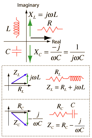
3. Impedance (Z)


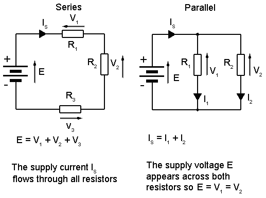
4. Series and parallel circuit


5.  Voltage divider (transfer function)

6. RC circuit ( low-pass and high-pass)

7. Active element realization


We also have to answer some problem related to series and parallel circuit including capacitors and resistors. Derivation of trigonometry functions is required to solve the problem.-->(Please mastering your M.A.T.H.S) There was also estimation method that we have to analyze in order to get it function, that is Doppler Signal Discriminator.

Doppler Signal Discriminator


8. Probe design

Example of probe design
Dr. Azran also had explained to us about molecular biology. The main point here is about cell staining. I do some research about this topic. What I understand is cell staining is a technique that can be used to better visualize cells and cell components under a microscope. For more information, please visit http://serc.carleton.edu/microbelife/research_methods/microscopy/cellstain.html. Here I put some pictures for cell staining :


Besides, he also shows us a video entitled 'Mechanics of Ascension'. This video tell us deeply about deoxyribonucleic acid (DNA) and its functions. There are so many DNA still not discovered yet, that also known as 'junk DNA'. 


We are also introduced to a winner of Noble Prize in Medicine in 2012. He is a Japanese physician and researcher of adult stem cells .He serves as the director of Center for iPS Cell Research and Application and a professor at the Institute for Frontier Medical Sciences at Kyoto University; as a senior investigator at the UCSF-affiliated J. David Gladstone Institutes in San Francisco, California; and as a professor of anatomy at University of California, San Francisco (UCSF). Yamanaka is also the current president of the International Society for Stem Cell Research (ISSCR). For more detail about him, please visit http://en.wikipedia.org/wiki/Shinya_Yamanaka

Shinya Yamanaka
Lastly, we also had been explained about the use of sonication treatment to completely decellularize blood artery. I also had search some information about this. Just definition it is. Sonication is the act of applying sound (usually ultrasound) energy to agitate particles in a sample, for various purposes. In the laboratory, it is usually applied using an ultrasonic bath or an ultrasonic probe, colloquially known as a sonicator. In a paper machine, an ultrasonic foil can distribute cellulose fibres more uniformly and strengthen the paper.
Please visit http://en.wikipedia.org/wiki/Sonication for more information :) .

That's all for today. I hope I can do my best to learn more about bioelectronics. I do not care even I have to study Biology as SPM. I learn from all my lecturers that we have to struggle and strive to achieve our goal.In addition,  I will not give up.  Because there is a success instead hardship :)

 "Although the road is long, we're going through it slowly."  -Anonymous-

Thanks a lot to Dr. Azran, Dr. Kamal and En. Redzuan :)


Thursday, October 25, 2012

Reflection 3

Ultiboard Has Made a Change :)

23/10/2012- This week we had learned how to convert from Multisim to Ultiboard. From the previous post, I had told you some about Multisim. Then this time I am going to tell you what is Ultiboard is about :) . In order to get a right information, I have done some 'googling'. Let me highlight here :


1. http://en.wikipedia.org/wiki/NI_Ultiboard:

NI Ultiboard or formerly ULTIboard is an electronic Printed Circuit Board Layout program which is part of a suite of circuit design programs, along with NI Multisim. One of its major features is the Real Time Design Rule Check, a feature that was only offered on expensive work stations in the days when it was introduced. ULTIboard was originally created by a company named Ultimate Technology, which is now a subsidiary of National Instruments. Ultiboard includes a 3D PCB viewing mode, as well as integrated import and export features to the Schematic Capture and Simulation software in the suite, Multisim.

2. http://www.ni.com/white-paper/5611/en

The NI Ultiboard interface enables efficient layout and routing of PCB designs. Integration with NI Multisim allows seamless transfer of schematics to layout. The customizable environment ensures accessibility to desired features for immediate productivity. Tools such as the spreadsheet view, toolbox and design wizards easily manage, control and define any board layout.


Part placement and copper routes are optimized to either allow full control for precise definition of critical parts or automation for quick design completion. The 3D preview renders a completed, populated board to gain a virtual perspective before production. Ultiboard exports and produces industry standard format such as Gerber and DXF to take a final, optimized board to prototype and manufacture.


The Ultiboard product editions (Full, Power Pro) provide a complete set of tools for professional PCB layout:

Intuitive, user-friendly design environment

Integrated spreadsheet view for managing design constraints, part placement, and copper routing

Easy-to-use design tools optimized for speed or precise control

Export to industry standard file formats such as Gerber and DXF for prototype and manufacturer.

In other words, Multisim and Ultiboard are closely related. Without the usage of Multisim, we cannot get the result in Ultiboard--> in form of 3D. Let me show you their closeliness :)

This is Multisim's front page :


In order to convert Multisim to Ultiboard, go to Transfer button. Select 'Transfer to Ultiboard', You will have this window appear:


This window is appearing in order to tell you what component you use and to confirm the number of component that you have use. After you click 'OK' button, the next window will be like this :


This step-by-step instruction had told you how the relationship between Multisim and Ultiboard. After done these 3 main steps, you can do whatever you wish for your Ultiboard. For example, I have finished design my components in the board. Have a look at this:


Then I convert it to 3D view. To do this, simply click 'Tools' then go to 'View 3D' button. This window will appear on your screen:


I also have captured some views from this 3D component. It included:
1. Upper view:
Upper view of 3D's component on the board.


2. Front view:
Front view of 3D's component on the board


3. The other side's view:
Other side of 3D's component on the board.

If I am not mistaken, this view is used for the soldering part. (For the next class, we will do some soldering and I cannot wait for that time! :) 

There are so many things have to be consider. In order to do some replacement of component, you will face some problem. This may include wrong connection of wire, DRC error (which the connection of wire is prohibited for some areas) and many more. Try to have a look on this circuit:

Some error of DRC.
The red arrows shows the errors that caused by the overlapping of point. You have to ensure that there is no DRC error before converting the diagram to 3D component. Otherwise, you will face some problem to do some changes on your circuit.

There are so many skills you have to learn to master this software. I have learned some of it, and this is the result I have obtained :)

Complete circuit :)

I will explain the diagram. The pink component means that component situated on the bottom of the copper layer. The other component without pink colour is situated on the upper of copper layer. The green wire means the wire situated on top of the copper layer. Also, red wire means the wire situated on bottom of the copper wire. Besides, the brown line means correct orientation for the component to connect. If you see any yellow wire, you have to made some adjustment. 

That's all for my workshop lesson this week. I am really interested to do more skills for this software. It challenges my mind and make me feel excited to explore more :) In order to be a professional engineer that will contribute to our lovely country, I will study hard! YEAH! 

- "Those who are successful are not those who failed in the attempt, not even those who often fail but those who never fail to try and keep trying until success we have achieved." - by Anonymous


Thanks a lot to Dr. Kamal and En. Redzuan :)


Monday, October 1, 2012

Reflection 2

It's all about MULTISIM :)

-Today's class start on 8:00 a.m. Why? (,'') --> Electronics subject, answer me!-


According to En. Redzuan, this week class will be held at Electronic Workshop. I am really excited when came to this workshop for this morning. There are many computers there, which I cannot sure; why in this workshop will have many computers. However, I expect to see some picture of electronics components with their functions; like diode, transistor, capacitor and etc. But it is not bad with '5S rules' and 'What You Have to do when getting electric shock' explanation on the whiteboard . Some of these all rules makes me be really careful for anything might be happen in the workshop.

OK, that's all about Electronic Workshop that I can tell and feel the environment. Now, let's get started with En. Redzuan's class. Today, we are going to run Multisim software. MULTISIM? (,'') What kind of that software? Such a weird name. But we all are really lucky having En. Redzuan to brief some of the usage of this Multisim. He started with the introduction to Multisim. Actually this software is under National Instruments Corporation. You can refer this website in order to know more about NI.. http://en.wikipedia.org/wiki/National_Instruments .. --> Ask Mr. Wiki XD! After that, we started to search for some skills in Schematic Capture. This included 1. Opening and saving files. As you have been familiar with Microsoft's software such as Powerpoint, Word or Excel, you can use your experience using them to the same way as you open or save files in this software. There's no difference. Plus, you also can choose to save your project first or after your project done. But watch out for some PC, there will be some trouble in order to save your project. En. Redzuan had told us the software always get 'hang' and you cannot save your project if that problem arise. (Thank Allah, my PC really kind on me for this time :) ). 2.Placing the component. After all have been done about open and save files, we are going to place some electronics components with the given diagram. Oh, I almost forget. Once we enter the class this morning. En. Redzuan had spread one worksheet, that is WORKSHOP 2. There are two diagrams available there, but we only have to do the one without IC 555. The components that involves in this diagram is LED, transistor P-N-P and N-P-N, capacitors and also resistors. There also one buzzer involve, but we just ignore it as on request from En. Redzuan. (I also don't know whether the buzzer will works or not).

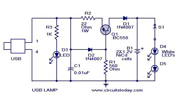
Example of electronic circuits.


That diagram just an example of what we had done this morning. There is a problem arise in order to get a real one picture. (Just use what I have :) ). The next is, 3. Wiring the circuit. In order to make sure the circuit functions well, we have to connect all the components in order to make it be a complete circuit. En. Redzuan had reminded us to be careful when we are going to connect from one component to another component. If you are unable to build correct connection, you will face some problem in stimulation step.
( My circuit works well with blinking LED :) . After we done the first three steps, we have to test our circuit whether it is functions or not. This is the last step, that is 4. Analysis. In this step, you have to make sure your component is connected correctly. You will see the result when the LED 'blinking' once you click 'run' on Stimulate options.

That's all about MULTISIM today :) I am really happy to get know on it. This software is about to train me to be a skillful and patient people. (Nice, isn't it? XD). I know it's not simple to use this software, but as a saying goes, 'Practice makes perfect' :) Just keep training and I'm sure I can do more connection on circuit diagram for the next workshop! (Insya Allah :D)

Before I leave this blog, I am glad to insert some of electronics component that have been use for our lesson :)

Transistors
Resistors
Diode
Switch SPST type
Power supply 9V

Capacitors


*Hard work will definitely pay off* 
-Kawato Koichi-

Thanks a lot to Dr. Kamal and En. Redzuan =)


Tuesday, September 18, 2012

Reflection 1

- First Lecture :) -

For the first time I attended class of Introduction To Electronic System (11/9/2012) I met Dr.Kamal as my lecturer. I am not happy to sit at the back (have to move faster next time) in order to hear what he want to say. It's a good surrounding since I met all SMJE students there :] --> including seniors (Diploma students).
I have to learn a lot from them. Please be kind on me :D.

At that time also, Dr. Kamal asked us, "Why Electronics?" Actually, when I heard this question, I have many things to tell him, --> I had learned C, C++ and Arduino software and build them with hardware. I also love to create new function of these software. I am hoping that I will never give up to do more research on this subject. I am interested to learn more. I am really happy to join this course in order to invent something for next generation (insya Allah).

Being there-in the class for three hours doesn't make me feel bored. Thanks a lot to all coursemate, I hope we can do our best to achieve our goal. TQ :)